The 6.6L Duramax employed the Garrett model GT3788VA variable geometry turbocharger (VGT) from 2004.5 to 2016 (LLY, LBZ, LMM, LML engine generations). The turbocharger utilizes a series of hydraulically actuated "vanes" to perpetually adjust the effective size of the turbine housing and the direction of exhaust gases, thus allowing the engine ECM to control the spool characteristics, manifold pressure (boost), and in the absence of a wastegate, prevent the turbocharger from overspeeding. A turbocharger overhaul is necessitated anytime the turbocharger is disassembled. The most common problem that warrants disassembly is to correct a mechanically seized unison ring or VGT vanes, but other conditions include:
• Bearing wear, chatter between the compressor/turbine and housing, or excessive end-play in the turbine/compressor wheel shaft
• Leaking oil seal(s)
• Compressor or turbine wheel damage
• Low boost condition that is determined to be the turbocharger assembly (compressor/turbine leaks, other physically damaged components)
Rebuilding the turbocharger on a Duramax diesel is somewhat intimidating the first time, but requires only basic hand tools and our comprehensive instructions below will guide you through every step in great detail.
Duramax Diesel Turbocharger Rebuild Parts List
Part Description |
Part Number(s) |
Remarks |
|
GT3788VA bearing & seal kit |
Garrett 740659-0010 |
[1] |
|
VGT solenoid (actuator) |
Qty (1) req |
||
Vane position sensor |
Qty (1) req |
||
VGT piston seal |
-012 Viton square profile o-ring |
[2] |
|
VGT pinion gear roll pin |
3 mm x 30 mm roll pin (coil type) |
--- |
|
Turbo coolant line crush washer |
Qty (2) req |
||
Turbo oil supply line crush washer |
Qty (2) req |
||
Turbo oil drain line upper gasket, 2001 - 2010 |
Qty (1) req |
||
Turbo oil drain line upper gasket, 2011 - 2016 |
|||
Turbo oil drain line lower gasket, 2001 - 2010 |
Qty (1) req |
||
Turbo oil drain line lower gasket, 2011 - 2016 |
|||
Compressor housing o-ring |
Garrett 403069-0252 |
[3] |
|
3M Roloc arbor, 1/4 in |
[4] |
||
3M Roloc conditioning disc set |
|||
High temperature anti-seize lubricant |
ACDelco 10-4039 |
[5] |
|
Complete turbocharger assembly |
LLY/LBZ |
GM 19329916 |
[6] |
LMM |
GM 19329915 |
||
LGH |
GM 12640123 |
||
LML |
GM 12677684 (new) |
||
[1] - Includes journal bearings, thrust washers, o-rings, shaft seals, etc.
[2] - Viton fluoroelastomer o-rings offer the greatest resistance to heat and oil exposure; do not use Buna or silicon o-ring. Quantity (2) required, can be reused if not damaged.
[3] - Compressor housing o-ring not included in bearing/seal kit and must be acquired separately; reuse is discouraged.
[4] - Or equivalent conditioning discs; use of sandpaper or heavy abrasives is discouraged. The 3M Roloc product line has become the industry standard in cleaning VGT vane assemblies, unison rings, and turbine housing surfaces.
[5] - High temperature anti-seize lubricant is required; listed products all rated at 2,400 °F.
[6] -
Part number is for factory remanufactured turbo unless otherwise noted. If turbocharger center cartridge, compressor housing, turbine wheel, or turbine housing is damaged, it may be more cost effective to replace the turbocharger than to attempt to rebuild it.
How to Disassemble the Turbocharger
Click any thumbnail to view fullsize, detailed image

• Place the turbocharger on a clean workbench. Be prepared for it to leak both oil and coolant as the bearing housing (bearing/center cartridge) drains.
• If not already completed, remove the vane position sensor and VGT solenoid/actuator.

• Remove the coolant feed and return lines from the bearing cartridge. A 17 mm socket is required to remove the banjo bolts; discard the corresponding crush washers, they are not to be reused.
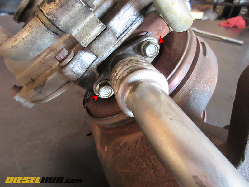
• Remove the engine oil drain tube from the bearing cartridge using a 12 mm socket (2 bolts); pry off carefully as not to damage the drain tube flange.
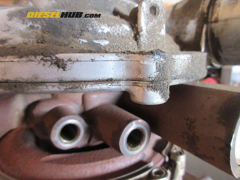
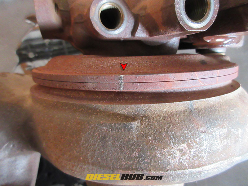
• Index the compressor housing to the backing plate by scribing or drawing a line so that the two sections can be reinstalled in the exact same orientation they were removed. Create another reference line to mark the orientation of the compressor housing backing plate relative to the center housing. It is preferred to use a scribe or engraving tool to make relatively deep marks that will not wash off when the turbo is cleaned.

• Index the turbine housing clamp to the turbine housing so it can be repositioned in the same orientation during reassembly, then loosen the clamp.

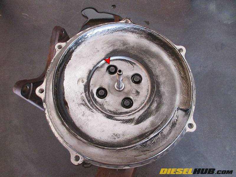
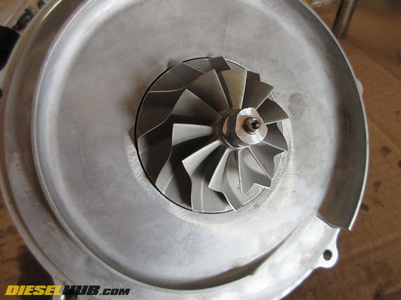
• Remove the compressor housing to backing plate bolts with an 8 mm, 12 point socket. Carefully separate the compressor housing from the backing plate without binding the compressor wheel. A putty knife, razor blade, thin chisel, and assortment of small flat blade screwdrivers work well. Spin the compressor wheel frequently to ensure it is not binding as you separate the two parts as this may severely damage the compressor wheel.

• Remove the compressor wheel by holding the turbine wheel in place with an appropriate socket to keep the shaft from spinning. THE COMPRESSOR WHEEL IS LEFT HAND (LH) THREAD, THUS IT WILL NEED TO BE ROTATED CLOCKWISE TO LOOSEN. A 17 mm socket fit the head of the compressor wheel and a 7/8 in socket fit the turbine wheel on our particularly turbo, however the sizes do vary and you will need to verify you are using the correct socket/wrench combination.
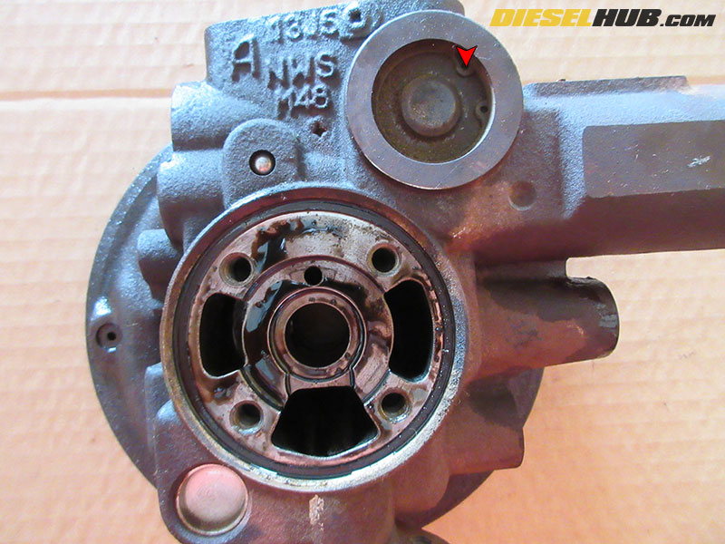
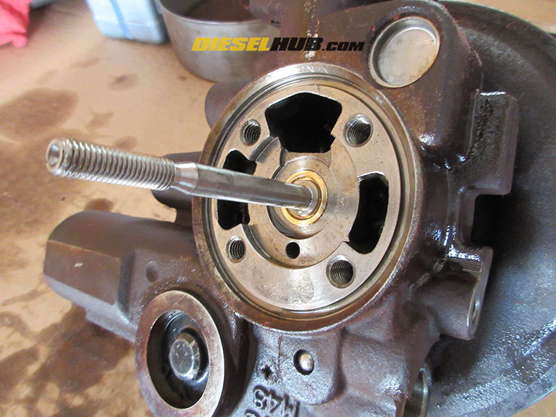
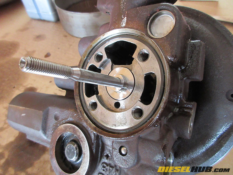
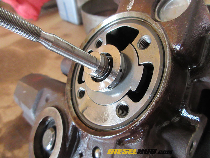
• Remove the compressor housing backing plate using an 8 mm, 12 point socket (4 bolts). When sliding the backing plate over the shaft (which will likely have the thrust bearing and washer attached to the rear), be extremely careful not to mare the shaft.
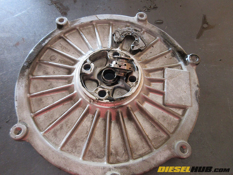
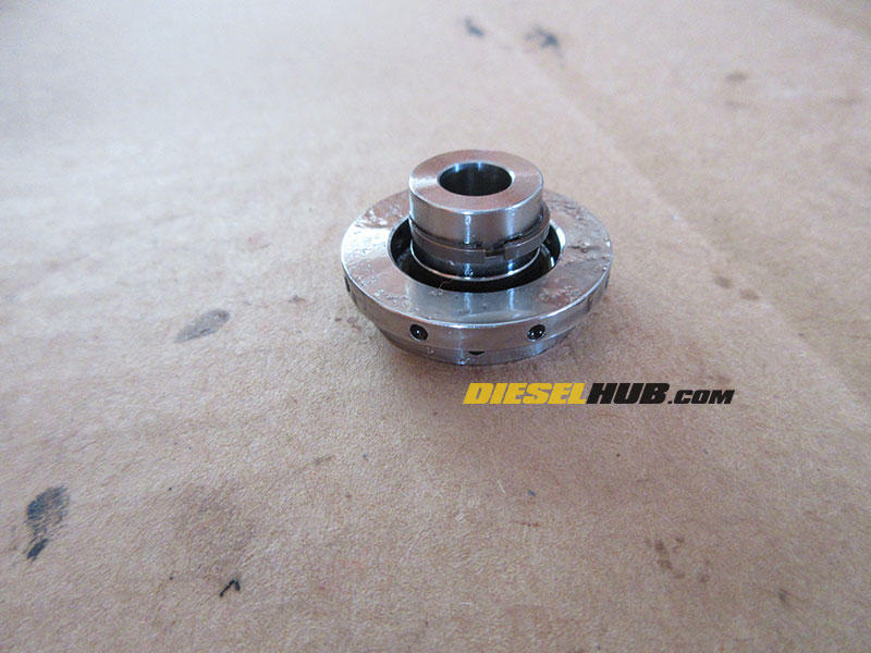
• Remove the thrust washer and bearing from the backing plate or bearing housing (it may have stuck in either location, or could have simply fell out during disassembly). Discard these items, they are not to be reused.

• Remove the compressor housing backing plate o-ring. There have been some suggestions that it can be reused, however we always advise that it be replaced; it is an inexpensive item but must be purchased separately from the standard service kit.
• Remove the turbine housing clamp; it may require that you remove the nut from the T-bolt to be able to maneuver it over the bearing housing.
• Index the turbine housing to the bearing housing/center cartridge so that it can be repositioned in the same orientation during reassembly.
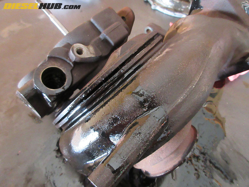
• Generously spray the flange where the turbine and bearing housings mate with a penetrating fluid (PB Blaster, WD-40, etc) and let it soak for several minutes.
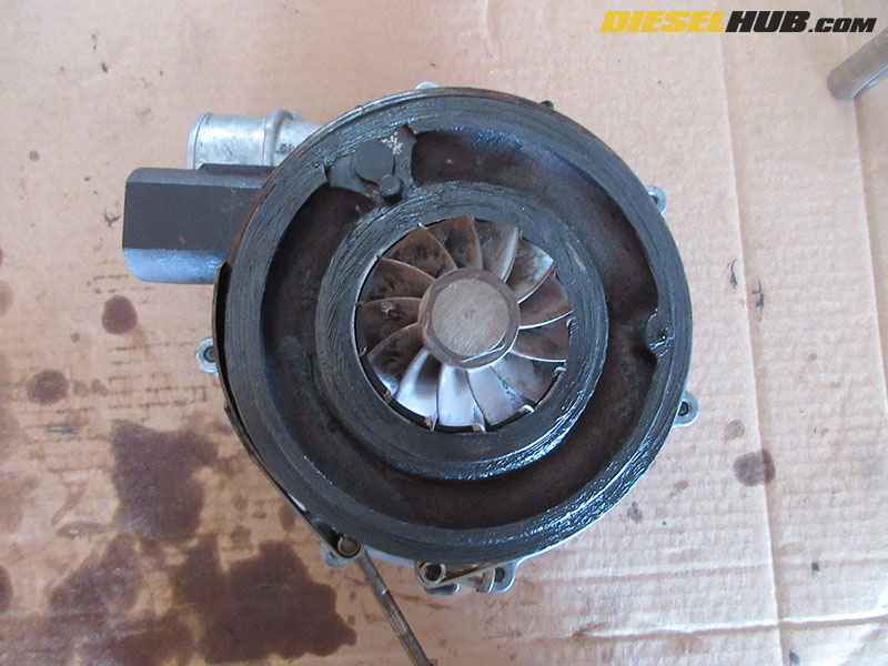
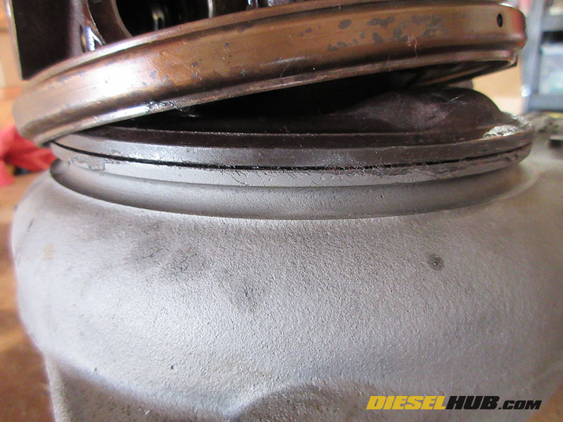
• Separate the bearing housing from the turbine housing without allowing the turbine wheel to bind. As with removing the compressor housing, separate the two halves in small increments while frequently verifying that the turbine wheel rotates freely. To start separating the two housings, hold the bearing housing securely and forcefully tap the turbine housing with a plastic dead blow mallet. Once the two halves begin to separate, a series of small screwdrivers and/or cold chisels can be used to complete the separation. Be extremely careful not to put any weight or strain onto the shaft during this process. Note that unless the turbine housing outlet is laying flat on the workbench the unison ring and vanes are going to fall out when the turbine housing is separated; don't be alarmed, we'll index these parts later.
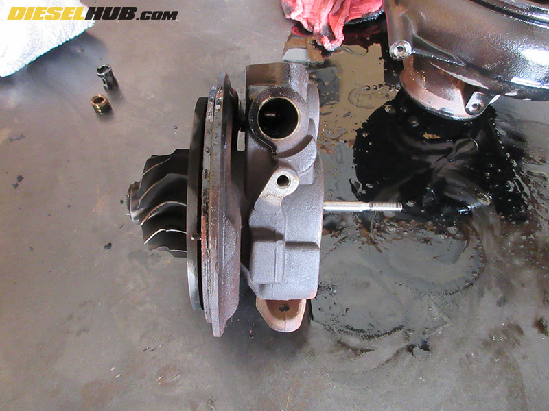
• Remove the turbine wheel/shaft assembly by gently tapping it with a plastic hammer; very little force is required.

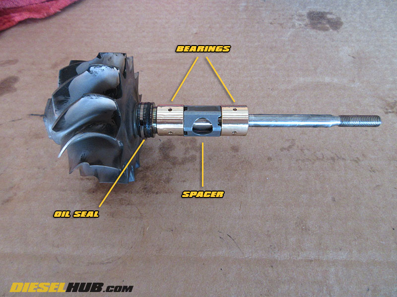
• Remove the oil ring from the turbine wheel using a small pick. Do not mare the shaft or the oil ring land. Note that this area needs to be thoroughly cleaned before reassembly or the new ring may not seat properly. Set the turbine wheel/shaft and compressor wheel in a safe spot.
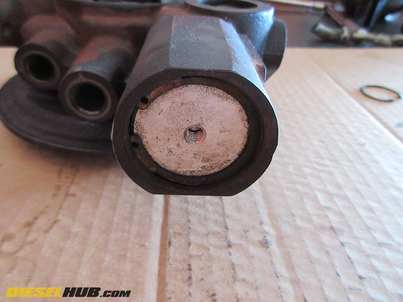
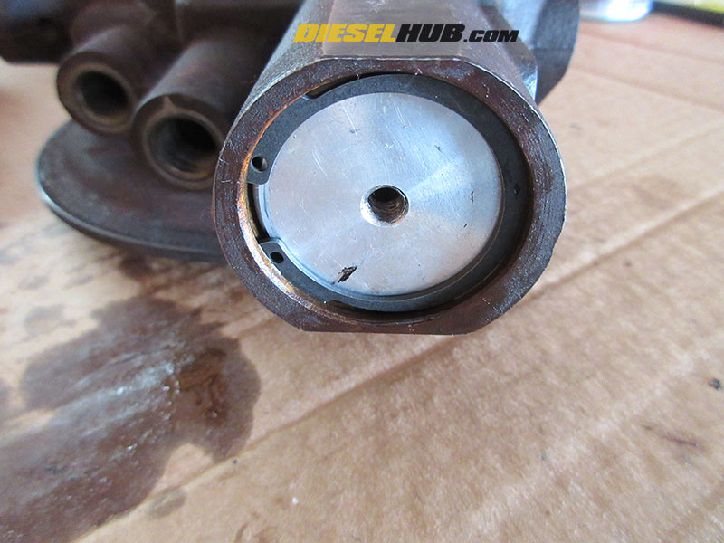
• Remove the snap ring securing the cap to the VGT actuator piston bore, then remove the aluminum cap itself. An M6 bolt will thread into the cap and aid in pulling it without marring the internal bore surface.
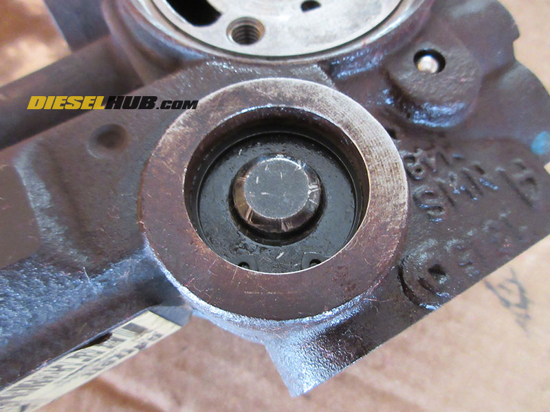
• Remove the snap ring securing the access cap to the VGT actuator gearset, then remove the cap.
• Remove and discard the backing plate o-ring from the bearing housing (note that it may have already fell out).
• Remove the o-ring that seals the VGT gearset access cap; discard, it is not to be reused.
• Disassembly of the VGT actuator gear assembly is OPTIONAL. Doing so will require two additional o-rings not included with the service kit. If you do not wish to service this system, do NOT remove the actuator piston and do NOT spin the actuator arm (doing so will spit the piston out of the bore and you will have to replace the o-rings). Reinstallation and indexing of this system is covered in subsequent steps.
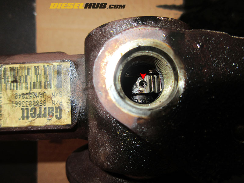
• If removing the VGT actuator gear, rotate the actuator armature clockwise 360 degrees, then remove the actuator piston from its bore.
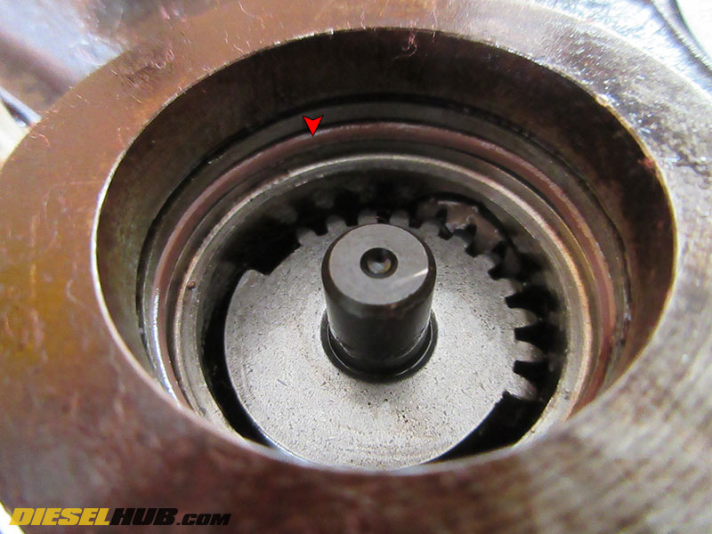
• Rotate the actuator armature once more until the roll pin is visible through the threaded vane position sensor hole. Use a small punch to drive out the roll pin, then remove the gear and armature for cleaning.
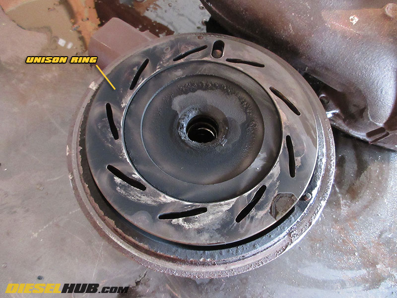
• It is common for the unison ring to seize to the face of the bearing housing; simply pry it off and set aside.
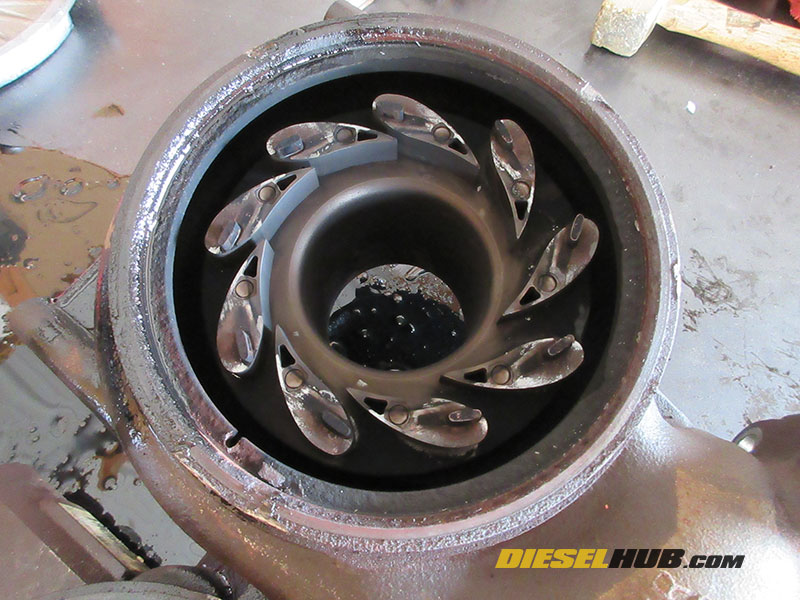
• Remove the VGT vanes and unison ring (if not already done so) from the turbine housing.
• Thoroughly clean all parts using an appropriate parts cleaner. If reusing the compressor housing o-ring and/or VGT actuator piston o-rings (this is common), do not clean them with or allow them to come into contact with a solvent based parts cleaner such as brake cleaner; it will chemically melt then.
• Do NOT attempt to scrub the compressor or turbine wheels; clean with a solvent. If a more thorough cleaning is desired, use an ultra-sonic cleaner. Compressor wheels with excessive wear marks or ANY damaged fins must be replaced.
Before continuing to the reassembly section below, please see:
6.6L Duramax Unison Ring & VGT Vane Cleaning (required)
How to Reassemble the Turbocharger
The following procedures assume that all components have been thoroughly cleaned, the unison ring and vanes have been indexed and installed in the turbine housing, and if applicable the VGT actuator piston has been reinstalled and indexed to the armature.
Note - Reassembly should only be performed in a CLEAN workspace to avoid possible contamination and/or infiltration. Unless otherwise noted, all o-rings are to be coated in clean engine oil before installation. We recommend filling a small, clean container with engine oil and soaking all o-rings, bearings, oil rings, and the thrust washer prior to installation.
• Install the new o-ring onto the aluminum VGT piston/actuator cap, then reinstall the cap with the new snap ring; both parts are included in the service kit.
• Install the new o-ring for the VGT actuator gear access cover, then install the cover using the new snap ring provided in the service kit.
• Install the new metal oil ring (seal) onto the turbine shaft (near the inner face of the turbine wheel where previously removed). Do not mare the shaft while installing the seal.
• After soaking the journal bearings and spacer in clean engine oil so that they are well coated, install them onto the shaft (bearing, spacer, followed by the second bearing).
• Slide the shaft through the bearing housing from the turbine side. Press firmly until the turbine oil ring snaps into place; it typically produces an audible "click" indicating that it has sealed properly.
• Coat the new compressor housing backing plate o-ring with clean motor oil, then install on the bearing housing flange.
• If not already done so, lubricate the small half of the thrust bearing in clean motor oil, then install over the shaft (see image for installation orientation).
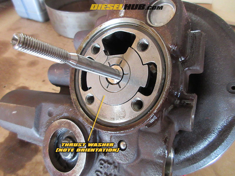
• Lubricate and install the thrust washer over the shaft. See image for installation orientation - it is extremely important that the thrust bearing is not installed backwards. The surface with a series of machined grooves must face into the bearing housing, NOT towards the backing plate.
• Carefully install the new oil ring seal onto the thrust bearing; lubricate well before installation.
• Install the thrust bearing onto the turbo shaft so that the oil ring/seal faces the compressor housing backing plate.

• Line up the compressor housing backing plate using the reference marks made prior to disassembly, then install the (4) backing plate bolts. Ensure that the thrust bearing oil seal properly seats into the backing plate by pressing the backing plate tightly (and evenly) against the bearing housing prior to installing the backing plate bolts. Torque bolts to 144 in-lbs (12 ft-lbs) in a crisscross pattern.
• Install the compressor wheel and torque to 120 in-lbs (10 ft-lbs). Recall that the compressor wheel is reverse thread, i.e. tighten counter-clockwise.

• Line up and install the compressor housing using the reference marks made prior to disassembly. Torque the compressor housing bolts to 144 in-lbs (12 ft-lbs) in an alternating pattern.
• Coat the unison ring and turbine housing mounting surfaces of the center section with high temperature anti-seize.
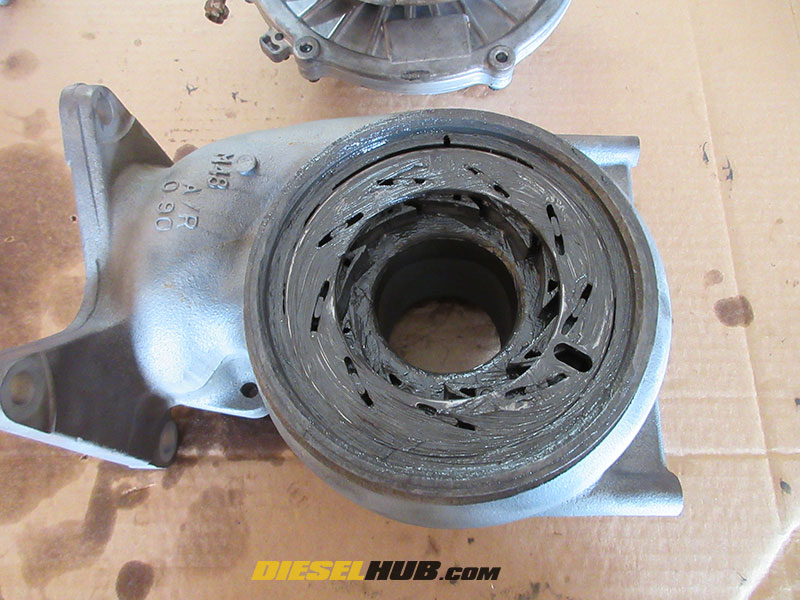
• If not already completed, assemble the VGT vanes and unison ring in the correct position; coat all components with high temperature anti-seize. See VGT cleaning and unison ring indexing procedures for detailed instructions.
• Install the clamp onto the bearing housing.
• With the turbine housing stationary on the workbench, align and install the bearing housing using the previously etched reference marks. It may be necessary to adjust the position of the unison ring/vanes for the actuator pin to line up correctly. Do not rotate the armature excessively in either direction or the piston may become unmeshed from the armature gear. It's ideal to find the center position on both the unison ring/vanes and armature pin.
• Once the turbine housing is installed and no parts are binding (turbine wheel to housing, unison ring and pin, etc), use a plastic mallet to fully seat the two halves.
• Align the clamp with the index mark(s) on the turbine housing, then torque to 160 in-lbs. Loosen the clamp, then torque to 50 in-lbs. Tap the perimeter of the turbine housing several times using a plastic dead block mallet and torque the clamp to 150 in-lbs.
• Reinstall the oil drain tube (torque to 89 in-lbs) and coolant lines (torque banjo bolts to 19 ft-lbs). We recommend installing the VGT solenoid and vane position sensor after the turbocharger has been reinstalled.
Note - after the turbocharger is reinstalled on the engine, you will need to pre-lube the turbo bearings by pouring CLEAN engine oil through the oil feed line hole while rotating the compressor wheel by hand.
Page Information
Last update: 12/7/2021
Copyright: Diesel Hub (dieselhub.com), all rights reserved
Disclaimer(s): Vehicle diagnostic and repair procedures may place participants in a situation that poses severe risk of injury; always adhere to proper safety guidelines, ensure any applicable safeguards are in place, and wear appropriate PPE when working on or around a vehicle.
Source(s): ACDelco parts catalog (part numbers), Garrett GT3788VA spec sheet (torque specs)